Navigation
SP25M installation
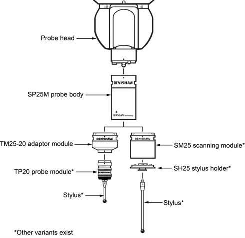
NOTE: All SP25M system components are identified with an engraved product name.
The front of each system component can be identified by the position of the Renishaw logo and the small alignment marks (where applicable).
Observe the kinematic mating faces between the SM25 scanning modules and each respective SH25 stylus holder. Each stylus holder kinematic face features four balls, three of which are arranged in a triangular formation which form one half of the kinematic joint between the stylus holder and each respective module. The fourth ball is positioned so that only the scanning module and respective stylus holder can be fitted and used together.
When installing and using the various system elements it is essential that the kinematic joints are clean and free from contaminants. Please refer to the maintenance pages for further cleaning instructions.
Renishaw probes and associated systems are precision tools used for obtaining precise measurements and must therefore be treated with care. The SP25M probe body and scanning modules are liable to irreparable damage if dropped or mistreated.