Navigation
Electrical specification
All of the PICS signals are with respect to the 0 V pin 3 of the 9 pin ‘D' connector.
PDAMP, PPOFF, STOP
These are bi-directional active low signals that conform to TTL electrical levels.
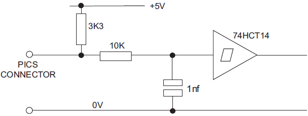
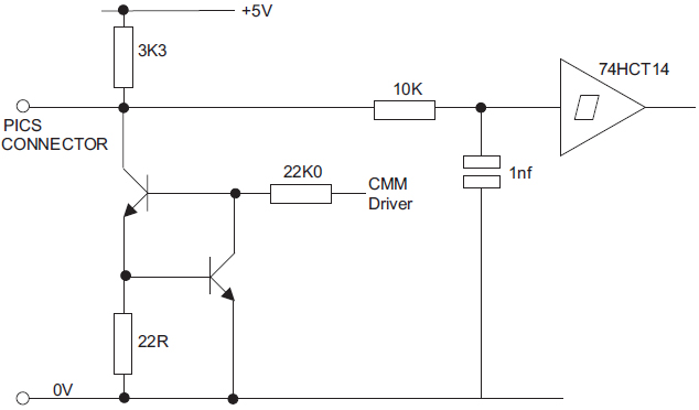
If the CMM uses any of the signals as an input, it must use the appropriate resistor terminations and a Schmitt trigger receiver conforming to TTL levels, such as 74HCT14.
SYNC, HALT, ERROR
These signals are unidirectional active low signals that conform to TTL electrical levels.
If the CMM uses any of the signals as an input, it must use the appropriate resistor terminations and a Schmitt trigger receiver conforming to TTL levels, such as 74HCT14.
LED OFF
This signal passes through all products and is connected to the LED anode in the probe head or probe head controller. Any product can turn off the LED by connecting LED OFF to 0 V.
Termination resistors must not be used, but a series current limiting resistor of between 39 Ohms and 56 Ohms is strongly recommended.
0 V
This is the common reference for all other PICS signals.
Screen
The screen connection is between the shells of all the interconnection cables.
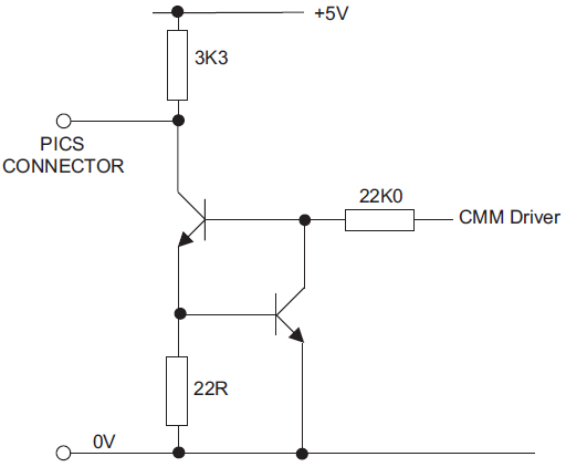
Suggested CMM controller terminations
Receiver circuit
For SYNC, HALT, ERROR signals.
Driver circuit
For READ signal.
Bi-directional circuit
For PDAMP, PPOFF signals.
STOP circuit
For STOP signal.
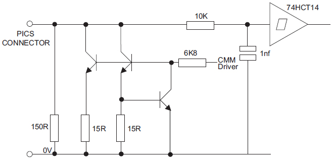
Drive circuits must be capable of sinking 15 mA, except STOP which must be capable of sinking 50 mA.
To ensure correct operation over the maximum recommended cable lengths, the output drivers must be capable of pulling down to less than 0.47 V.
The STOP driver must be capable of pulling down to less than 0.34 V.